3D Print Files: 34m Deep Space StationDownload Free of Charge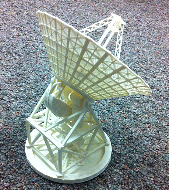
This 1:250 scale model of a 34-meter diameter Beam Waveguide (BWG) Deep Space Station completes the picture. It prints easily without needing any support material or rafting. It illustrates the antenna's mechanical structure and its microwave beam-waveguide system. It shows correctly how the dish rotates in azimuth and elevation above-grade, while the waveguide tubes articulate to reflect radio signals to and from the receivers and transmitters, which are located below-grade (not represented in the model). The BWG stations are the newest design in NASA's Deep Space Network (DSN). There are several in place in the Deep Space Communications Complexes at Goldstone, California, Madrid, Spain, and Canberra, Australia, and more ar being built today. Four of them, when electronically arrayed, can reproduce the gain and performance of one 70-meter diameter station. Together, these exquisitely precise ground stations comprise the thousands of tons of concrete and steel which constitute the "other end" of basically every interplanetary spacecraft. This model was designed to reproduce key aspects of a DSN station at least an order of magnitude better than the free downloadable paper version. There are six print files (.stl), which contain a total of ten parts to be printed using white ABS plastic, about 65.3 cm3 in all. The parts fit together easily and are to be welded in place using a few drops of acetone. The main reflector piece takes a good bit of careful bending and clamping and waiting after it's been printed. Here are thumbnails of the six part files, courtesy of Tinkercad.com.
Differences from the Real DSN AntennaThis scale model shows the main load-bearing structural design, but it does not show all of the platforms and handrails and stiars that the real antenna has. It correctly shows how the microwave system's beam-waveguides work, down to the diagonal periscope-like mirrors internal to them, but it does not show a truly parabolic shape in the main reflector. Nor does the main reflector show the enormous amount of 3D detail that it might. (If you'd like to improve upon its design, go to Tinkercad.com, search for "BWG-Main-Reflector," and please honor the stated license.) The model shows the elevation-drive motor and how it interfaces with the elevation-drive gear. It shows the elevation bearings fairly. In the model's azimuth bearing, the pintle is not differentiated from the waveguide, which of course are different structures in the real antenna. The azimuth trucks are shown flat with the alidade base, but in reality the alidade rides up atop the four azimuth trucks. Finally, the subreflector mounting system at the apex of the quadrapod is simplified to enable printing at all.Download Free of ChargeLeft- or right-click (as appropriate for your browser) to download each of the following linked files (total of all six files is 3.4 megabytes):
For printing using FDM, this model requires only a single-extruder machine. No support material needs to be generated. Print using white ABS plastic. The main reflector dish requires an 8-inch print platform, but all the other parts may be printed on a 4-inch platform.
Assembly Instructions[ ] Have a look at how a real DSN BWG Deep Space Station is built:
[ ] Set your slicer and/or printer to print each part WITHOUT any "raft" below the part. Use the following configuration settings:
[ ] Weld the waveguide into position on the bottom of the Upper Alidade as shown:
[ ] Use a tiny amount of acetone to make your welds in the ABS plastic. Less than a drop is enough for welding the waveguides together. Use a needle applicator like this one, available from plastics supply stores or art supply stores:
[ ] Fit the Lower Alidade into place, oriented as shown, matching up the corner slots and pegs. Weld with a drop of acetone at each corner. The waveguides will begin to form their "periscope." No need to weld the waveguides together.
[ ] Weld the Counterweight onto the Elevation Assembly trusses. Make sure to line up the "teeth" of the Elevation Gear. Note for a future step: the blue arrows point to the Elevation Bearing pintles.
[ ] Bend the Main Reflector around on itself to make a cone. Ridges face outside. Overlap, weld, and clamp as shown. Give it plenty of time to cure before unclamping; overnight might be a good amount of time.
[ ] Fit the Subreflector Support (it looks like a little 4-legged table) down over the apex of the Quadrapod and weld in place. Weld the flat side of the Subreflector dome onto the four support legs.
[ ] Once the Main Reflector has cured thoroughly, remove the clamp(s). You might need to adjust it into an even cone shape by heating carefully with a hair drier and pressing gently onto a flat surface. Once you're satisfied with its shape, fit it onto the Elevation Assembly as shown, and weld in place with drops of acetone.
[ ] Center the Quadrapod into the Main Reflector with the Subreflector directly above the central waveguide hole. Rotate the rectangular base so that its longer dimension is in line with the Counterweight. Now gently clip off the rectangular support, being very careful not to break the delicate Quadrapod. Weld the four feet onto the Main Reflector. Clip the Elevation Bearing pintles into the Upper Alidade (see yellow arrow), and you're done. Congratulations!
[ ]
Oh. One more thing. Set the whole thing down onto the Aximuth Track, matching up the center waveguides.
|


