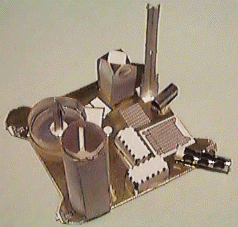
Mars Global Surveyor Space Craft SCIENCE Kit
Assembly Instructions

Version 1.5.html
A. YOU'LL NEED THE FOLLOWING:
Small scissors, such as manicure scissors, to clip parts from the Parts Sheets.
Wooden toothpicks for applying glue.
A round pencil or dowel for wrapping curvature into some parts.
One or two toothpicks, or a paper clip cut to short lengths, will be needed for structural support in your model.
A small pair of long-nose pliers (or needle-nose pliers) to squeeze some parts together while they glue.
Glues. Use regular white glue (Elmer's Glue-All or equivalent). You might also try a thick white glue, sold in art and fabric stores, called "TACKY GLUE" (Aleen's or equivalent).
Space. Set up a well lighted, comfortable work area, with room to set glued parts to dry.
Time. Set aside several hours for unhurried assembly. About 4 hours would be minimum.
Patience. While much of this kit assembles easily due to its advanced design, there may be a few trying times. Extra care will pay off with a surprisingly accurate, and handsome representation of NASA's Mars Global Surveyor spacecraft.
Optional: A hair dryer might be useful for setting glue in some steps. Using it for just a minute will set a film on the surface of glue joints, which will hold parts in position for further air-drying. If you choose to use a hair drier, be very careful not to blow the paper parts apart, or to scatter them.
Optional: Cylindrical propellant tanks are represented in your model by intersecting flat parts. For more realism, you might want to locate or fabricate some 3-dimensional objects to replace them in your model. Hobby stores, even bead stores might be helpful.
B. BEFORE BEGINNING ASSEMBLY:
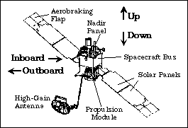
Unfold the Fact Sheet to the diagram of the spacecraft under "MGS Spacecraft Description" and use as a reference during assembly.
Examine the four Parts Sheets, A, B, and two C/D, and read the names of all the parts. The two Sheets C/D are identical.
Read all the instructions before starting to work. Compare model parts with the illustrations.
Configurations: This model kit describes five basic spacecraft configurations. You'll need to choose one configuration to assemble. The Mapping configuration alone represents full deployment of spacecraft appendages, and is the default in this set of instructions. Steps marked "(MAP)" are performed differently for other configurations, and will refer you to the Presentation Guide for what to do. Perform all steps, including all the "(MAP)" steps, if you're assembling the mapping configuration.
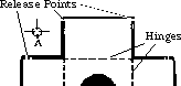
Notice the RELEASE POINTS to be snipped to remove parts. Identify HINGES which join segments of some parts for folding.
Get your bearings: this diagram defines "up," "down," etc. for the purpose of assembly. The model is shown assembled in mapping configuration.
Sections marked with a * may be accomplished at the same time if two or more people are working on assembly, or if you wish to work on one section while glue dries on another.
If you have any specific suggestions for improving the wording of these instructions, please send mail or e-mail to SCI. Thank you.
* 1. ASSEMBLE THE SPACECRAFT BUS
Release the SPACECRAFT BUS from Sheet A, being very careful to clip ONLY the release points. Lay it gold-side down on your work surface. For information about the spacecraft, compare the printed detail with the illustration on the Fact Sheet: these details will soon be closed inside.
Hold the central square down, and fold up one of the rectangular sides. Crease its hinge by folding the side panel all the way over onto the central square, and unfold again. Repeat with the three remaining side panels.
Fold the four side up panels 90 degrees to the central square, gold facing out, and engage the tabs and slots to hold their positions. Secure with glue.
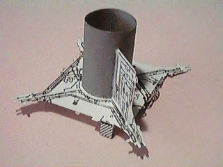
* 2. ASSEMBLE THE PROPULSION MODULE SUBSYSTEM (PMS)
On the front side of Sheet B, look at the PMS BASE and the PMS CYLINDER. Notice how three black lines (representing propulsion system tubing) on the PMS CYLINDER are pointing toward the center of the PMS BASE. On the right side of the PMS BASE's central hole, three black lines meet the hole, on its right side. This is how the CYLINDER will align inside the BASE later.
Notice the four "arms" of the PMS BASE extending out from the BASE's corners. These support small rocket thrusters on the spacecraft. The thrusters are represented by tiny tabs, three at the end of each thruster arm.
Release the PMS BASE from Sheet B, and hold its front side facing you (the front side has the letters P, H, and Y). Fold the large rectangular tab Y down, making a crease on the black line where it meets the PMS BASE below the slanted black lines. Put a crease in its middle, on the black line above the slanted lines, and fold Y further down.
Insert the tiny tab Y into the hole marked X on the back side of the BASE. Secure with glue, but avoid getting glue into the slot marked with an arrow. This part is designed so the side with slanted lines is not exactly perpendicular with the BASE; it points slightly outward. Avoid crushing this triangular member during further assembly.
Release the PMS CYLINDER from Sheet B. Roll it into a cylinder, with the black lines facing out, by bringing the white end around to meet its opposite end. Roll it around a pencil to fold in a nice even curvature. Before gluing it, insert it into the central hole of the PMS BASE, and adjust the cylinder for maximum diameter, to fit snugly within the central hole. Make a pencil mark to show exactly how much of the ends need to overlap. Remove, apply glue to the white end, and secure the PMS CYLINDER into an even tubular shape. Let the glue dry.
Insert the black-marked end of the PMS CYLINDER down into the front side of the PMS BASE. It should be a snug fit. Insert it just enough that about a millimeter of the black marked end pushes through. Rotate the CYLINDER until its three black lines meet up with the corresponding three lines printed on the PMS BASE (near five tiny printed rectangles). Secure the CYLINDER there with glue, exactly perpendicular to the BASE.
Set the PMS BASE down, with the cylinder facing up. The triangular member can hang over the edge of a table to keep the BASE flat.
From one Sheet C/D, release the one of the PMS VERTICALS closest to its label. It has a greater area of printed detail than the other. The edge which is nearest the label is the bottom edge. The edge at right angles to the bottom is the inside edge. Trim off any remnants of the release points.
Place the PMS VERTICAL down onto the PMS BASE with its inside edge touching the PMS CYLINDER, and its bottom edge touching the PMS BASE, its tapered section pointing out the middle of the thruster arm of the PMS BASE closest to the folded triangular member Y. Glue in place and let dry, keeping the PMS VERTICAL exactly perpendicular to the PMS BASE.
Repeat the above step with the same piece from the other Sheet C/D, installing it on the opposite arm of the PMS BASE. Let the glue dry, then repeat with the remaining two PMS VERTICALS. Make sure all four VERTICALS are perpendicular to the BASE.
Two small white tabs point outward from the end of each arm of the PMS BASE, representing thrusters. Fold all 8 of these 90 degrees downward. The remaining thrusters, pointing sideways, should not be folded.
Release the PMS CONE from Sheet B. Smear some glue onto the white triangular section, and pull it around to close the triangular gap, forming a cone. Overlap and squeeze the seam, holding until the glue dries. It may help to squeeze using long-nose pliers. When the glue dries, adjust the shape of the part into an even cone shape.
Hold the PMS BASE with its back side facing you (cylinder down). Drop the PMS CONE down into the end of the PMS CYLINDER to close it off, inserting the pointed end of the CONE down into the CYLINDER. Secure with glue, adjusting to keep the CONE evenly centered.
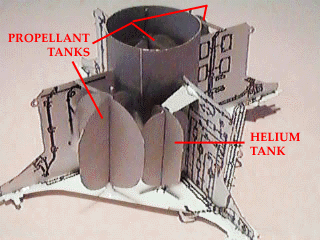
From Sheet A, release the two halves of the PROPELLANT TANK. Slide them together, slot into slot, perpendicular with each other. Secure with glue. This assembly represents a cylindrical tank with domed ends.
Holding the PROPELLANT TANK by the long tab at one end, insert the tank down inside the long end of the PMS CYLINDER until it rests on apex of the the CONE at the bottom. Secure with glue.
From one Sheet C/D release both halves of the PROPULSION TANK. Slide them together, slot into slot, perpendicular with each other. Secure with glue. This assembly also represents a cylindrical tank with domed ends (note: the name is slightly different only to avoid confusion with the above steps).
Repeat the above step with the PROPULSION TANK HALVES from the other Sheet C/D.
OPTION: You might want to locate a pair of 3-dimensional objects, perhaps from a bead store, to use instead of these PROPULSION TANK assemblies (see also the HELIUM TANK, below). They should all be colored titanium grey if you do.
One end of each PROPULSION TANK has a small tab. Insert this tab down into a hole marked P on the PMS BASE. Line it up straight and parallel with the PMS CYLINDER, resting against it, perpendicular to the PMS BASE. The long tab should rest up against a PMS VERTICAL. Secure with glue. When dry, repeat with the other PROPULSION TANK.
From Sheet A, release the two halves of the HELIUM TANK. Helium is used to pressurize the propellants on the spacecraft. Slide the tank halves together, slot into slot, perpendicular with each other. Secure with glue.
Fold the large tab over 90� to the tank. Fold down the tab's end section, marked with a white line at its end, another 90�. With this folded tab facing up, set the HELIUM TANK down onto the hole marked H on the PMS BASE. Turn it so the tab will contact the nearest PMS VERTICAL. Glue the tab there to support the tank, and glue the bottom of the tank to the PMS BASE. Keep the tank straight and parallel to the PMS CYLINDER.
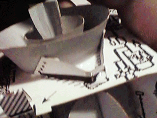
Release the OUTER HEAT SHIELD from Sheet B. Apply glue to the white end, and overlap it onto the opposite end, forming a conical band. Make sure the seam is straight. Hold until the glue dries. Using long-nose pliers will help. Adjust the band's curvature into an even shape, as much as possible (the band is not exactly conical - our goof).
Repeat the same procedure with the INNER HEAT SHIELD from Sheet B.
Fit the small diameter end of the OUTER HEAT SHIELD down around the bottom lip of the PMS CYLINDER where it protrudes through the PMS BASE. Secure with glue.
Fit the small diameter end of the INNER HEAT SHIELD down into the PMS CONE, concentric with it and the OUTER HEAT SHIELD. Secure with glue. Refer to the illustration in the Fact Sheet.
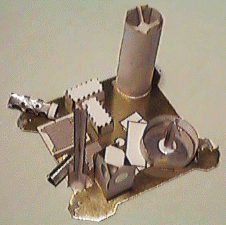
From Sheet B, release the MAIN ENGINE HALVES. Slide them together, slot into slot, perpendicular with each other. Secure with glue.
OPTION: You might want to locate a tiny bell-shaped 3-dimensional object to use instead of this assembly. It should be colored grey or black if you do.
Set the small end of the MAIN ENGINE down into the center of the PMS CONE, inside the two concentric HEAT SHIELDS. Stand it up, parallel to the PMS CYLINDER, secure with glue.
Release the TANK SUPPORT from one Sheet C/D, and trim off any remnants of the release points. Grasp the center grey section with long-nose pliers, and fold back the two "bow-tie" ends to meet each other, then release.
Stand the PMS CYLINDER on end, so the bottom of the PMS BASE faces up. Notice two pairs of dotted lines. Place the TANK SUPPORT down onto these dotted lines, with its black edge touching the dotted lines. The small center section of the TANK SUPPORT should be close to the hole marked P on the PMS BASE. Its two wide ends (with 4 holes) should touch the OUTER HEAT SHIELD. Secure it there with glue, twisting the ends slightly to flatten onto the OUTER HEAT SHIELD. Let the glue dry.
Repeat the above step using the TANK SUPPORT from the other Sheet C/D.
3. MATE THE SPACECRAFT BUS TO THE PROPULSION MODULE
Fit the SPACECRAFT BUS's central hole down onto the PMS CYLINDER, with the gold panels facing upward. The base of the SPACECRAFT BUS should come into flush contact with the tops of the PMS VERTICALS. If necessary, trim off the tops of the PROPULSION TANKS so the SPACECRAFT BUS will seat properly.
Rotate the SPACECRAFT BUS so that its -X side (with the silver louvers) is facing the side of the PROPULSION MODULE which has the HELIUM TANK. Align the SPACECRAFT BUS squarely over the PMS BASE. The PMS VERTICALS should be right under the SPACECRAFT BUS's corners. Secure into position with glue.
* 4. ASSEMBLE THE NADIR PANEL
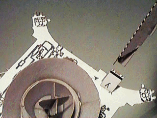
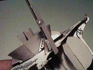
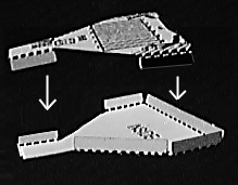
Refer to the images of the completed NADIR PANEL, located at the end of this section, for help in understanding the following instructions.
Release the NADIR PANEL from Sheet A, and set it down gold side up.
Release the MOC TELESCOPE from Sheet B. MOC stands for Mars Orbiter Camera. Trim off any release point remnants. Wrap it around a pencil, the edge with the slanted markings parallel to the pencil, forming a cylinder. Apply glue to the slanted markings, and overlap to form the cylinder. It will help to squeeze the seam with long nose pliers. Adjust its shape into an even cylinder.
Release the MOC ELECTRONICS rectangle from Sheet B. Apply glue down the center on its marked side, and attach it to the MOC TELESCOPE tube, along its seam. It should remain flat, and tangent to the tube. Adjust to be even with the cylinder.
Release the MOC SPIDER from Sheet A. Holding its silvered side down, bend its four arms toward the non-silvered side, back about 40 degrees. The silver dot represents the secondary mirror of the MOC's cassegrain optics.
Place the MOC SPIDER silver down, into one end of the MOC TELESCOPE tube. One arm should point toward the seam. Using the eraser end of a pencil, gently push the SPIDER down into the tube until the arm ends are just inside. Straighten, and secure with glue.
Place the MOC TELESCOPE onto the NADIR PANEL, centering the tube over the small silver circle (which represents its primary mirror). The flat MOC ELECTRONICS should hang slightly over the edge of the NADIR PANEL, parallel with it. Secure with glue.
Release the CSA (Celestial Sensor Assembly) from Sheet A. Wrap around a pencil (or toothpick) to form a tube, with the thin black line parallel to the pencil. Glue into a tube shape.
Set the CSA tube down onto the NADIR PANEL on the white box marked CSA, aligning it to the angle of the white box. The white end of the CSA faces inboard. About half of the silver end protrudes off the edge of the NADIR PANEL.
Release the ER (Electron Reflectometer) from Sheet A. In a similar manner, make a tiny tube of it, wrapping it in its longer dimension to overlap. Glue it down to the ER box on the NADIR PANEL, aligning to the angle of the box, about half of the ER protruding over the edge.
Release the HORIZON SENSOR from Sheet A. Fold down its 4 flaps away from the silvered side, toward making a rectangular box of them. Place a slight bend below each silver circle to enable a rectangular box to form. Glue the sides of the box together, keeping them as perpendicular as possible.
Glue the completed HORIZON SENSOR down onto the NADIR PANEL, centering it over the white box marked HSA (Horizon Sensor Assembly).
Release the MOLA BAFFLE from Sheet B. MOLA stands for Mars Orbiter Laser Altimeter. Apply glue to the marked end, and overlap to make a circular band. Squeeze the seam, and adjust the band to become as circular as possible.
Glue the MOLA BAFFLE band down onto the NADIR PANEL so that it surrounds the large silver circle. The silver circle represents the MOLA optics primary mirror. It's also a Cassegrain telescope.
Release the halves of the MOLA SECONDARY from Sheet B. Trim off release point remnants. Fit the parts together at right angles, slot into slot, and secure with glue. This represents the assembly which supports the secondary mirror. The mirror itself is not represented.
Dip the narrow end of the MOLA SECONDARY in glue, and stand it up on the white dot in the center of the silver MOLA mirror on the NADIR PANEL. Coax it to remain perpendicular to the NADIR PANEL while the glue dries.
Release the halves of the MARS RELAY ANTENNA from Sheet B. Trim off any release point remnants. Fit the parts together at right angles, slot into slot, and secure with glue. Dip its large end in glue, and stand it up in the white box marked MR on the NADIR PANEL.
Your NADIR PANEL might be warping slightly because of the wet glue, causing various instruments, such as the MOC, MOLA, and MR to point in slightly different directions. This illustrates why the NADIR PANEL on the spacecraft was designed very carefully to remain very flat. It is an "optical bench." Your NADIR PANEL will probably flatten out again when all the glue has dried completely.
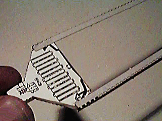
Release the INSTRUMENT ELECTRONICS BOX from one Sheet C/D. Fold its panels down to make a rectangular box. Glue this piece down onto the NADIR PANEL, closed end up, covering the white rectangle marked TES. This box will represent the Thermal Emission Spectrometer (TES).
Release the INSTRUMENT ELECTRONICS BOX from the other Sheet C/D. Fold its panels down to make a rectangular box. Glue this piece down onto the NADIR PANEL, covering the other white rectangle perpendicular to the TES. This box will represent the Magnetometer/Electron Reflectometer electronics assembly.
Here are two views of the completed NADIR PANEL from different directions.
|
|
* 5. ASSEMBLE THE HIGH-GAIN ANTENNA
From Sheet A, carefully release the large, irregular shaped HIGH-GAIN ANTENNA. Be very careful to only clip the 11 release points.
With the gold side up, smear a small amount of glue along the white edge of the triangular opening in the gold circle. The glue should be beside the edge, going outward from the center. The glue should not extend all the way to the gold.
Fold the gold circle into a shallow cone, with the gold outside, overlapping the gold circle onto the glue, leaving a white line similar to the two other ones on the gold part. Be careful not to destroy any of the pieces attached to the circle. Squeeze together using long-nose pliers, and hold until the glue dries.
Once the glue has dried thoroughly, place the gold side down on a flat surface, and gently press down from the grey side with your thumb, to cause the white point of the cone to crush slightly into a rounded, blunt shape. Be careful not to crush much more than the white point of the gold cone.
Release the two halves of the FEED HORN from Sheet A. Slide them together at right angles, slot into slot, and secure with glue.
Insert the small end of the FEED HORN into the central hole in the grey inside of HGA cone. Secure with glue, keeping it centered within the cone, standing straight out, as glue dries.
Find the rectangle labelled HIGH-GAIN ANTENNA on the piece. Notice it has other rectangles hinged to it. Fold these up into a box, enclosing the words. Fold and insert the long tab into the slot near the edge of the cone, and twist to lock it in place, to help keep the box's shape. Adjust so all the sides of the box are perpendicular, secure with glue, and let dry. This represents the box containing the transmitting amplifier on the spacecraft. It's called a Travelling Wave Tube Amplifier (TWTA, pronounced "Tweeta").
Just above the wording 'HIGH-GAIN" (now enclosed) notice a thin black line within the circular part. Fold along that line to bring the TWTA box around so its open side covers the white crescent above the thin black line. Apply glue to secure the open side of the TWTA box to the gold cone. See the photo on the front of Sheet A for guidance.
Two grey struts connect the small circular Subreflector (marked SR) to the gold cone. Crease these where they meet the gold cone, and bring the SR over FEED HORN. Crease all 3 struts where they join the SR. Connect the end of the free strut into the hook on the edge of the gold cone, and secure it there with glue. Adjust so that the SR is centered flat above the FEED HORN. You might have to bend back the glued, engaged hook to get the subreflector centered.
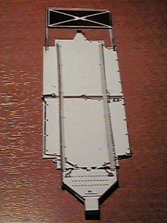
* 6. ASSEMBLE THE SOLAR PANELS
(Skip this entire section if you're assembling your model in Launch Configuration. See Presentation Guide for further instructions).
Release the SOLAR ARRAY YOKE HALVES from one Sheet C/D. On each, fold all 6 hinged rectangular panels down toward the side marked "inside," leaving them folded at 90-degrees. One half has eleven rectangles printed on it. This will be called the TOP half. On the TOP half, notice heavy black lines printed along the outside of two of the six folded rectangular panels. Smear glue on the outside of those two folded panels.
Turn the two pieces so the sides marked "INSIDE" face each other, and fit them together, making a "box." The two rectangular panels with glue (marked black) fit inside the corresponding white rectangles on the counterpart. Smear some glue on the black rectangular panels of the bottom half, and fit them inside of the mating panels. Align to make a nice even box of the yoke, and press the glued panels together.
Adjust the remaining folded rectangular panels perpendicular to the large flat surfaces of the yoke, and apply glue to complete the box. Recheck after glue dries, to be sure all the panels are glued in position, adding glue if necessary, so the yoke "box" will be fairly strong.
Release the SOLAR ARRAY YOKE HALVES from the other Sheet C/D, and assemble as above.
Release the SOLAR ARRAY AND AEROBRAKING FLAP part from one Sheet C/D. Notice the two light-grey hinged panels which support the gold aerobrake flaps. Using a straightedge, fold the outer hinged panels lengthwise down away from the blue side, leaving them about 90 degrees to the large panel surface.
Set the panel down on a flat surface, blue side facing down, hinged panels facing up. Notice a short dotted line where your hinged panels connect with the larger white area. This location will need a bit of extra structural support: Cut a toothpick (or some rigid wire, like a paper clip) to about a centimeter (half an inch) in length, and glue it parallel to one of the dotted lines, connecting the light grey arm to the white area so it won't be able to flex. Repeat on the other side, parallel to the other dotted line.
Release the two SOLAR ARRAY SUPPORTS from one Sheet C/D. Note: these parts do not exist on the spacecraft. They are only used to support your model's solar panels here in Earth's gravity. Notice an area of slanted lines near one end. Using a straightedge, fold each support along its hinge (lengthwise) into an L-shape cross section, folding the slanted line sections toward each other.
Smear some glue on the small slanted line sections of one SOLAR ARRAY SUPPORT. Press it onto the corner of one SOLAR ARRAY YOKE marked with slanted lines. Adjust to point straight out from the yoke.
Do the same with the other SOLAR ARRAY SUPPORT, on the opposite side of the YOKE. Adjust so it is parallel to the other SUPPORT.
Set your SOLAR ARRAY AND AEROBRAKING FLAP assembly blue-side down on a flat surface, with the inboard end (the end opposite the gold flap) pointing toward you. Notice three little appendages coming off the inboard end. The tips of these appendages are to be covered by the YOKE.
Smear a very thin coat of glue along the top of each SOLAR ARRAY SUPPORT. Turn the YOKE upside down, the three rows of printed dots facing up, the glue facing down. Set this down onto the SOLAR ARRAY so the edge of the YOKE overlaps the three appendages from the SOLAR ARRAY just slightly. Adjust the edge of the yoke parallel to the edge of the SOLAR ARRAY near it. Press the SUPPORTs down so the glue will bond the SUPPORTS to the SOLAR ARRAY as depicted. Keep the SUPPORTs straight and centered on the SOLAR ARRAY.
When the glue dries, turn the SOLAR ARRAY over, blue side up. Apply some glue to the three appendages where they meet the YOKE. The black appendages represent electrical cables; the central white one represents the deploy mechanism.
Release SOLAR ARRAY/AEROBRAKE FLAP, SOLAR ARRAY SUPPORTS from other Sheet C/D, and assemble as above. p Release the SOLAR ARRAY DRIVE MOTOR from one Sheet C/D. Apply glue to the marked end, overlap the opposite end onto it, forming a circular band. Squeeze the seam, let glue dry.
One edge of the SOLAR ARRAY DRIVE MOTOR band has curved notches so it can mate to the PMS CYLINDER. Dip this edge in glue.
Place the SOLAR ARRAY DRIVE MOTOR against the +Y side of the PMS CYLINDER, aligning the band's notches to fit the cylinder. Place it up high on the cylinder, so the top of the band will touch the bottom of the SPACECRAFT BUS. Add plenty of glue to fortify its attachment.
Repeat with the remaining SOLAR ARRAY DRIVE MOTOR, installing it on the -Y side of the PMS CYLINDER. This completes solar array assembly.
7. ATTACH THE NADIR PANEL
Set the NADIR PANEL down on top of the SPACECRAFT BUS, instrument side up. Rotate so that the MOC TELESCOPE is directly above the silver louvers on the -X side of the SPACECRAFT BUS. Align the NADIR PANEL squarely over the SPACECRAFT BUS and secure with glue.
8. ATTACH THE SOLAR PANELS
Follow these instructions if you're assembling your model in Mapping Configuration. Otherwise, skip this section and see Presentation Guide.
(MAP) Look at the Solar Arrays in the photo on the front of Sheet A. This illustrates one possible way to position the arrays for mapping configuration. They may be oriented with the blue side facing most any direction, but both arrays will allways be facing the same direction. They will be in the same plane, or parallel with each other.
(MAP) Lay the spacecraft on its side, insert the small end of a SOLAR ARRAY YOKE into one SOLAR ARRAY DRIVE MOTOR. Apply a little glue where they join. Do the same on the other side, with the other SOLAR ARRAY YOKE. Line up the solar panels the way you want them, with both facing in exactly the same direction (see photo on Sheet A for one suggested orientation). Note: the solar arrays can move up and down (+ and- Z) and rotate about their long axis. They cannot move side to side (+ or - X). Adjust so they're in line with one another.
(MAP) Once the glue has dried, apply a good amount more glue inside each SOLAR ARRAY DRIVE MOTOR to provide a strong attachment. Let dry thoroughly.
9. ATTACH THE HIGH-GAIN ANTENNA (HGA)
Follow these instructions if you're assembling your model in Mapping Configuration. Otherwise, skip this section and see Presentation Guide.
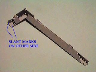
(MAP) Release the HGA STRUT from Sheet B. Notice one side has slanted lines marked on two tabs. Keeping this side down, fold up, in the opposite direction, all 4 panels which are hinged to the central L-shaped piece. Engage the four little tabs into their corresponding slots, and secure with glue.
(MAP) Fold back the two tabs marked with slants, and apply glue to them on the side opposite the slant marks. Press these onto the area marked with slants on the gold side of the HGA, aligning the boom to point away from the TWTA box.
(MAP) Hold model with main engine pointing up, and locate triangular support Y. Insert the end of the HGA STRUT down over the support, so that the small slot near the end of the boom engages the slot marked on the PMS BASE by an arrow. See illustration.
(MAP) Apply glue to the slant marks on support Y, and press the inside of the HGA STRUT against it. Apply more glue to fortify the attachment.
THIS COMPLETES YOUR MGS MODEL.
ABOUT YOUR MGS MODEL
It is made of 100% recycled paper. Its scale is about 1/40. The HGA Boom is much thicker than scale, so tht it can support the HGA in Earth's gravity. The two positioning motors at the end of the HGA Boom, where they attach to the HGA, are not represented very well, for simplicity. The HGA can swivel to point almost any direction on the actual spacecraft. Thermal blanketing covering propellant tanks is not shown on your model so tanks and other detail may be visible. One outboard solar panel on the spacecraft never locked in position (as of May, 1997). See the MGS web site for details (url is listed on the Fact Sheet).
Now that you're familiar with the names of all of the spacecraft's major structures, and some of its instruments, the enclosed fact sheet will point out the rest of the instruments, and explain what everything on the spacecraft is for.
Sections marked with a * may be accomplished at the same time if two or more people are working on assembly, or if you wish to work on one section while glue dries on another.
|TOP OF PAGE|