Fabricate the Copper Hub
Fabricating the copper hub is the most complex step in this Advanced Version of your scale model. It should be fairly easy, though, for someone who has some skill soldering and working with small metal pieces. Before starting this step, read all the instructions to get a sense of what is being accomplished.
If necessary, adapt these instructions to work with any parts you are using that might be different from the nominal ones listed. The blade Connection Rods are referred to as "Bamboo Skewers" on this page. You may be using a different item, such as a miniature dowel. The basic idea is to have blade Connection Rods that fit snugly inside the hub's tubing, but not so tightly that they cannot be twisted inside the tubing.
Besides this copper hub, all the other steps are similar to the Basic Version model.

- Review the list of items you'll need, from the first page of these instructions.
- Cut your copper tubing into four lengths of 1 inch each. Inspect the cut ends to be sure they're clean and open. If necessary, insert the pointed end of a bamboo skewer to clean the openings.
Recall that the copper tubing you use needs to mate with the bamboo skewers (or miniature dowels) as mentioned in the first page of these instructions.
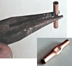
- Using a pair of long-nose pliers, pinch the middle of each section of copper tube to flatten it.

- Take one copper disk (or copper-clad disk) the size and thickness of a U.S. penny, 3/4-inch in diameter (we'd just say use a penny if it were legal to deface currency), and clean both sides using a rubber eraser.
Drill four holes in it, about equally spaced, inward a little from the edge... about 1/16-inch to 1/8-inch inward.
- Clean and drill a second disk in the same way.

- Cut a piece of bare 18-AWG copper wire (slightly thinner is ok) to a length of about 4 inches and bend it into a U. Insert the ends through two opposite holes in the metal disk.
Cut another piece of wire and insert it in the other holes.

- Insert two sections of copper tube beneath the wire loops, at right angles to each other. Pull the loops tight while you adjust the copper tubes to lie perpendicular, and centered on the disk.
Use your long-nose pliers to twist the wires on the back of the disk to further tighten the assembly. Remove all the slack from the wires, so the parts are all tight and straight. Adjust the upper-most copper tube so it is parallel to the disk.
Bend the wire tails on the back, and insert them in your vise to hold the assembly level while you proceed to solder.

- Solder the assembly. Use a 25-Watt soldering iron, touching the tip of the iron to the disk, and heating it until solder melts as you apply it to the work. Be sure the whole assembly gets good and hot, so that solder melts and flows wherever you apply it.
Do not "paint" gobs of solder on with the iron. It has to flow freely.
The image at right attempts to show the completed soldering job.

- On the back of the soldered disk, clip off the wires using wire cutters, leaving about 1/8-inch of wire protruding behind each of the four holes. With long-nose pliers, twist each of these tails into a U-shape pointing back toward the disk.
The intent is to provide some structure for hot glue to grab onto in a later step, so there should be some open space between the wire U's and the back of the disk.

- Repeat steps 6 through 9 above to make a second soldered disk-and-tube assembly. This time, however, before soldering add a loop of wire above the copper tubes, as shown in the image at right.
This will serve as a point to suspend your completed model for display.
- Brush off the back sides of both disk assemblies. Apply hot glue liberally to the back of both disks. Be sure the hot glue flows around the looped "nubs" of wire. Place the disks together back-to-back: the copper tubes of one must line up with the space between the copper tubes of the other. Only approximate alignment is required. At this point, it is not necessary to achieve good alignment.

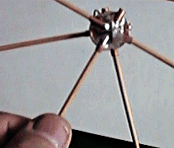
- Insert at least five bamboo skewers into the copper tubes, two in one disk assembly, three in the other, as shown at right. These will be used as indicators and also as handles while you adjust the alignment of both disk assemblies.
- Now for the alignment: Hold the disk assemblies in front of a hair drier, to re-heat the hot glue between the disks. Adjust the alignment of the disks, using the skewers as guides. Work them into an evenly-spaced alignment as shown at right. Also, align both disks parallel to one another.
Carefully move the assembly away from the hair drier and let the glue re-harden. Be careful not to move anything out of alignment before the glue re-hardens.
- When the glue is hard, remove all the skewers.
On to the Next Step...
BACK TO THE SCALE MODEL HOME PAGE

|


