THIS IS THE OLD SYSTEM VERSION, last updated October 10, 2004
Current version of the system is described here.

 In April 2002 I decided to design and implement a residential solar photovoltaic system for my house in Altadena (California). As of June 25 that year, the first version was finished. In a nutshell, it runs lights at night, and during the day it both feeds the utility grid and recharges the night-lighting batteries. The system, recently upgraded and simplified, produces and manages a little more than one and a half kilowatts.
During the decade that we lived on a 46-foot sailboat, we generated all our own electrical power from the Sun and wind, and rowed all our water out to the boat in 10-gallon jugs. So it seems natural for me to keep an eye on balancing a battery-based night lighting system, although it is mostly care-free. But the batteries are purely optional in a residential system; the only real reason to maintain them is having about eight kilowatt hours of backup 120-volt AC house current available in case of grid failure.
Solar electricity facilitates a distributed-generation philosophy, aimed toward reducing the need for new large-scale, and often environmentally harmful, central generating stations and distribution lines. My own objectives for the PV system are:
<soapbox>
We should not be using up resources that belong to future generations It's foolish and unethical to wage and provoke wars to "secure" control of those resources.
Our nation should be leading the world in creating for future generations an energy policy and and infrastructure based on clean, renewable sources -- instead of being led by powerful corporations blindly down a dead-end path. There's a nice stable nuclear fusion reaction taking place at just the right distance (150 million km) from us. All we need do is tap into it!
As I demonstrate, the technology is in place, and only needs large-scale implementation. It would be inexpensive and easy our national government to significantly reduce consumption of fossil fuels.
I feel it is criminal to present piles of nuclear waste to our next generations, saying, "Here, you kids figure out how to transport it and store it safely for forty thousand years, and don't let anybody do anything bad with it, ever; you kids please entomb all our old nuclear reactors for us; and by the way you can deal with acid rain from the coal we plowed up and wasted."
Today, renewable sources count for only two percent of the electricity generated in the U.S., while petroleum counts for three percent. Coal and nuclear are our main sources for generating electricity. Our transportation "system" is a whole 'nother story. I'm committed to doing what little I can to demonstrate that it's easy to meet our energy needs in a clean and sustainable way!
</soapbox>
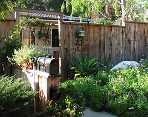
The image up there shows the entry to my house through the fence on the east; The Solar System is outside in the southwest corner of the back yard, within a 10 x 30 -foot area that I fenced off.
Even though my housemate Mitch flinches at the sound of that sorry old 1960's word, I've adapted the phrase to mean the electric meter here at the house is spinning backwards. "We're solar groovy!"
Solar Heated Water
The HotSpring brand hot tub I installed in August 2001 uses a 1.5kW electric heating element to heat the water. Its design is good in that it doesn't come in contact with the water and will therefore last forever-ish. But man, did it soak up those kilowatts. In winter, the temperature in the tub decreases four degrees Farenheit each night, so it used to keep burining up the electricity. Obviously, its conversion to solar water heating was a high priority. As of mid-January '03 it was done, and works very well. Selecting the system components, though, turned out to be very time consuming.
As for hot water for bathing, laundry, etc., I haven't endeavoured to convert from the natural gas-fired tank heater yet. Later on I might go ahead and convert from tank-type to demand-type to increase the efficiency. A solar water collector is in place on the roof now too, so I can work in to a vented, drain-down pv-powered heat exchanging system to pre-heat the household water. Meanwhile the fairly small usage, combined with the low price of natural gas, makes the task less of a priority.
 Of course there's a place outside the laundry room for hanging a few clothes on hangers in the sun. But for years I'd been wanting to figure out a way to force solar-heated air into a tumbling clothes drier.
First thoughts were always about how to make a solar hot air collector, and maybe buy an old clothes drier to convert. Then, one sunny afternoon I was crawling around the low attic space running wires, sweating by the litre. "Duh!" I realized what to do. It would be much simpler!
A 4-inch diameter hole, near the apex of the stucco firewall in the garage, was the first component. Then a bent-tin "manifold" went on the back of the drier to take over its air intake grilles. You can see that in the photo at right. A flexible duct now delivers hot, dry air from the attic space to the drier. A small fan inside the duct "turbocharges" the flow while the drier runs, to overcome the added path-friction. I'd like to think it requires burning less natural gas now, but I haven't tried to quantify results yet. At least you can decide to set it on "Air Fluff" in the afternoon and use only the solar-heated air.
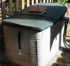
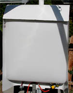
THE BATTERY BOX |
Eight deep-cycle golf-cart batteries (see the component list below) are hooked up in series-parallel to provide nominally 12 volts DC with a capacity of over 800 amp-hours. A 1.3-kilowatt inverter steps that up to 120 volts AC to power the lights. Golf-cart batteries are a popular choice for residential solar use, since they're pretty rugged and inexpensive. Regular automotive batteries are not a good choice since they're designed to output high current in a short period of time, rather than medium current over prolonged periods. The batteries live in a RubberMaid deck box that I got from Orchard Supply Hardware.
Electrical code requires a vent on top of the battery compartment to let the hydrogen escape when it dissociates from water in the cells when they are being charged. That's what that copper "hat" is. The batteries sit on a floor of concrete brick and gravel with some sodium bicarbonate mixed in, in case of any acid drips or spills. In the box there's also a 250-amp fuse and a big red disconnect switch made for boats by Perko.
The batteries connect via red and black 2-gauge cables that run ten feet to the electronics center through a one-inch PVC electrical conduit that you can see on the right side of the battery box. Behind the battery box is the low picket fence defining the utility area. Blackberries are assigned to use it as a trellis.
Thin-Film Amorphous Silicon Photovoltaic Panels
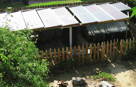
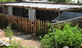
DAVE'S SOLAR SYSTEM -- EARLY VERSION (CLICK THE IMAGE TO SEE THE UPGRADED VERSION) |
The compost bin and the gardening toolshed sit below the solar panels, and blackberries grow along the waist-high picket fence. The twenty-four US64 panels are mechanically joined together end-to-end in pairs. They connect electrically into six 48-volt groups, each group wired to its fuse in the Xantrex 2500 grid intertie unit, which inputs them all in parallel. A 6-gauge bare copper wire binds all the panel frames to ground, for protection from electrical gradients produced by any thunderstorms that might come by over the years.
I mounted the panels at about a ten-degree slant facing south, just to let water drain off when it rains, and when I spray off the pollen, dirt, and guano with a hose. (After cleaning, I spray on a surfactant made for dishwashers to break up droplets of water, leaving an unobstructed surface to face the Sun.) The panels are unobtrusive, and provide some shade for the utility area. I decided not to try making any sort of variable-declination mount, which could rotate to lower angles in the winter sun, because of the challenge from the fierce northeast Santa Ana winds. Tracking the sun's daily movement in hour-angle was likewise way out of the question.
Each pair of series-wired US64s connects electrically via a short 14-gauge run of Romex into a conduit. There, series connections of two pairs of panels join their own 10-gauge wire pair for the longer run down to the Xantrex 2500 grid intertie unit.
The image below on the right shows the Xantrex 2500 grid intertie unit taking lots of 48VDC (nominal -- the unit's maximum power tracking algorithm determines actual operating voltage), and churning out 240VAC into the utility grid. The idea is called "net metering." The grid serves as a virtual battery that works at 120/240VAC. You "charge" the grid as you can, and use from it as you need, then pay the power company for any excess you use. Per the agreement, you have to forfiet any excess that you supply on a yearly net basis, so it wouldn't pay to install a monster system.
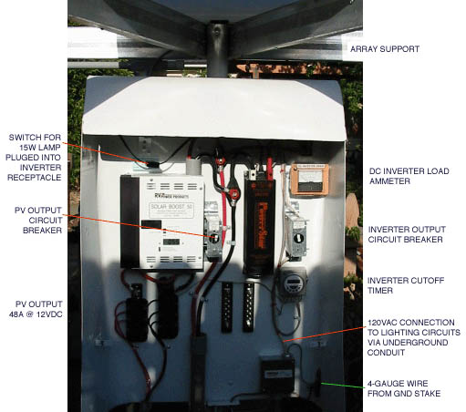
ELECTRONICS CENTER |
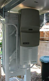
XANTREX INTERTIE |
COVERED |
The image on the right shows the rainproof cover in place over the electronics housing. The cover is actually from an old fluorescent ceiling-mounted light fixture, but it fits perfectly.
 on all but summer days. Plus, I wanted easy access to the panels topsides for cleaning and underside for easy connection work.
The steel structure that supports the US64s is made of 25-gauge steel channel fastened together into lightweight 2X4-inch box structures. It's supported on its east side atop a set of three 2-inch steel fence posts. Its west side is supported by 1.5-inch steel fence posts sunk into the masonry wall. 16-gauge angle iron goes between all the posts, for the box-steel members to rest upon. Most of the structural materials are from Home Depot. The wood sections you see along the east ends of the PV panels are just benderboard to reduce the severity of head-bonkings.
The image at left shows the array from just above eye-level, looking toward the southwest. You can see most of the structure, the north edges of the panel pairs, the intertie near the left side of the image, the electronics center and battery box near the middle, and the compost bin with its slanted corrugated steel cover on the right. (Tomatoes are growing vigorously in the lower right :-)
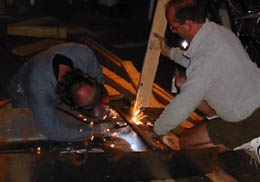
BENDING |
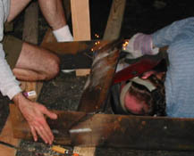
WELDING |
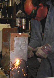
CUTTING |
| Component | Spec | Quantity | Source | Cost |
|---|---|---|---|---|
| PV Panel | UniSolar US64 | 21 | Solar Electric Inc, San Diego | $289 each |
| Battery | Trojan T105 Golf-cart, 215 AH | 8 | Solar Electric Inc, San Diego | $59 each |
| Battery Housing | RubberMaid Deck Box | 1 | Orchard Supply Hardware, Pasadena | $65 |
| Battery Charger |
IOTA Engineering DLS-45
(In the early version of the system, a dedicated set of PV panels fed a SolarBoost 50 which managed the batteries admirably, until I decided to re-configure the system.) | 1 | Solar Electric Inc, San Diego (who, by the way, permitted the exchange of the SolarBoost50 for nearly what I had paid!) | $189 |
| Night-lighting Inverter | PowerStar UPG1300 | 1 | Solar Electric Inc, San Diego | $279 |
| Digital Timer Switch | Seeley | 3 | RealGoods | $90 each |
| Weather housing for SplarBoost50 and 1.3kW inverter, timer, CBs, etc. | 16-gauge steel, bent & welded. H: 38 inches, W: 27 inches, D: 9 inches | 1 | Homemade | $20 |
| Utility Intertie | Xantrex/Trace Sun-Tie STXR2500 | 1 | Solar Electric Inc, San Diego | $1995 |
| Battery cables, switches, terminal strips, circuit breakers, fuse, ammeter | Various, marine grade | West Marine, Marina Del Rey | $200 total | |
| Steel Fenceposts for Support Structure | 2-inch dia | 3 | Home Depot, Monrovia | $6 each |
| Steel beams for Support Structure | 2x4-inch channel, 10-ft lengths | 30 | Home Depot, Monrovia | $1.79 each |
| Wire for PV connection | 10-gauge stranded | 250 ft | Home Depot, Monrovia | $ .10 per ft |
| Wire for connection to night lighting (house and landscape) circuits | 12-gauge solid | 300 ft | Home Depot, Monrovia | $.08 per ft |
| Conduit for connection to grid and night lighting circuits | 3/4-inch PVC | 200 ft | Home Depot, Monrovia | $.10 per ft |
| Wire for connection to the grid | 10-gauge stranded | 300 ft | Home Depot, Monrovia | $.10 per ft |
| Disconnect Switch | 3-pole | 1 | Home Depot, Monrovia | $18 |
| It's not finished until the paperwork is done! | ||||
| Electrical Permit | For connecting up to the grid | 1 | Los Angeles County Dept. of Public Works, Building & Safety | $126 |
| Net Metering Agreement | Needed before making the connection to the grid | 1 | Southern California Edison Inc. | Free |
| Buydown Reservation | For refund! | 1 | State of California | (Half the total excluding battery system) |
The end result: Pour all available solar-produced energy into the grid. Charge the batteries off the grid for use at night. When the batteries come up to charge early on a long summer day (see Schematic Diagram 1) no solar PV potential will go to waste while there's bright afternoon sun, as it used to with dedicated PV charging. Also, the batteries will be at their best each day no matter what the weather. This scheme also provides an emergency 1.3kW supply of 110VAC at all times!
Neither Schematic Diagram 1 nor 2 are correct any more. Watch this space for an update.
Solar Powerless in TexasThe November/December 2002 issue of Public Citizen News ["Winds of Change," p.1] contains a chart showing not only that Texas is No.1 in renewable energy potential, but also that Texas is No.1 in solar energy potential.In light of this fact, I should be generating lots of electricity from the solar panels I have installed on my roof. But no. The city of Kerrville, where I live, seems afraid to embrace this new technology. It is demanding $1 million in liability insurance against failure of my inverter that feeds power back into the city's power grid. The cost of such insurance would be more than I presently pay for electricity without any solar energy. Other cities accept this technology as proven and do not demand any such insurance. John J.B. Miller |
There are two PV panel sections: (1) a parallel 12V section hardwired to charge the battery for night lights, (2) a larger, series 48V section hardwired to power the intertie and slow down and reverse the electric meter. The two voltages are there because the lighting inverter requires 12VDC, while the utility grid intertie unit requires 48VDC. There aren't any inexpensive lighting-inverter choices for a 48VDC system!
The doggone AC-coil relay made a slight buzzing noise because of the step-form of the inverter's output wave. It could be just barely heard in the quietest part of the night (nights are usually real quiet here). One night it somehow started resonating, and the buzz became as loud as an alarm clock. It got replaced with a more complicated DC-coil version, that is quiet. I'm not going to update the diagram, but the DC coil is now supplied through a full-bridge silicon rectifier with a filter capacitor. Works fine.
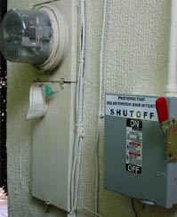 The Xantrex utility intertie unit's manual says to mount the intertie unit as close as possible to the electric meter. Well, it I were to do that I'd have to run bunches of heavy wire to carry the 48VDC from the solar panels over 125 feet! What with the distance, low voltage and high current, each wire would have to be mighty thick! No, the unit ties in across the distance via 240VAC on 10-gauge wire. As long as there's a clearly labelled disconnect switch close to the meter, the County electrical inspector, and the Utility Company, are happy. (Since there's already adequate disconnect and circuit-breaking capability in the intertie unit, the disconnect switch is technically redundant.)