|
ASSEMBLE AND INSTALL THE SECONDARY MIRROR SPIDER
View the whole assembled model
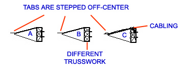
- From one Sheet DE, remove the 3 pieces labeled SPIDER 1/6. Notice that there are two kinds of trusswork. Notice also that one of the pieces includes simulated cabling. Also notice that the tabs at the tapered ends are slightly higher on the top than the bottom. Line them up on your work surface as shown below:
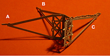
- Keeping the orientation exactly as shown above, lift the right-hand end of the A-part, bring its two white tabs over the B-part, and insert the tabs down into the B-part's slots. Crimp the tabs to hold in place. In the same manner, bring the B-part's tabs over the C-part in the orientation shown above, and insert the tabs down into the C-part's slots, and crimp the tabs to hold them in place. See below.
- From the other Sheet DE, remove the remaining 3 pieces labeled SPIDER 1/6, align and and connect them to each other exactly as in the previous step.
- Now join the two groups, inserting in the same way the white tabs from a C-part into the slots in an A-part. Complete a symmetrical, hexagonal ring of 6 pieces. Apply glue to each joint, inside the hexagonal ring, at its top and bottom, to hold the 6 pieces together. Let dry.
- Make a bend in each pair of legs - the long triangle - which extend out of the SPIDER's hexagonal ring. Bend so that the legs all radiate directly out from the center of the hexagon. This completes the SPIDER. The TOP of the SPIDER is the side where cabling appears, on two opposing legs.
+
+
+
+
+
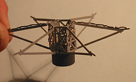
- From Sheet A, release the SECONDARY BAFFLE. Curl it into a cylinder, bringing its ends together. You may want to wrap it around a pencil. Work it into an even cylinder with ends touching or overlapping slightly.
Position one end of it up inside the bottom of the SPIDER's central hexagon. (Recall that the bottom of the SPIDER is opposite the cabling.)Adjust it so the cylinder's edge is just visible up inside the lowest truss in the SPIDER's hexagon, and most of the SECONDARY BAFFLE cylinder extends out the bottom. Glue in place.
- From Sheet A, release the SECONDARY MIRROR. Bend all its tabs 90 degrees or more, in a direction back behind the reflective surface. Insert the tabs up into the bottom of the SECONDARY BAFFLE, and work it in until the reflective surface is even with the lowest SPIDER truss, level, and facing straight down. Apply glue inside the SPIDER's hexagon to keep it there.
- Set the SPIDER down on top of the UPPER TELESCOPE TUBE such that one of the SPIDER's legs which has cabling rests atop the corner where cabling approaches the top of the UPPER TELESCOPE TUBE. The notch of the SPIDER leg should sit inside the UPPER TELESCOPE TUBE's corner.
Position the opposite SPIDER LEG, which also has cabling, into the opposite corner in the UPPER TELESCOPE TUBE. Fasten in place with a drop of glue in both corners. Let dry.
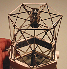
- Work another opposing pair of SPIDER legs into an opposing pair of corners at the top of the UPPER TELESCOPE TUBE. Glue and let dry, then repeat with the two remaining SPIDER legs. In the process, adjust the top of the UPPER TELESCOPE TUBE to be a neat hexagon.
Re-adjust the SPIDER if necessary, so the legs all radiate from the center of its hexagon. When the glue dries, trim off the portions of tabs protruding outside the UPPER TELESCOPE TUBE.
THIS COMPLETES ASSEMBLY AND INSTALLATION OF THE SECONDARY MIRROR SPIDER.
View the whole assembled model
| GO ON TO THE NEXT STEP |
| INSTRUCTIONS FIRST PAGE |
| SCI HOME PAGE |
|