|
Voyager SCIENCE KIT
Assembly Instructions for
LAUNCH CONFIGURATION
Version 1.2 For the SCI Web Site

You can, if you wish, assemble your Voyager Space Craft® SCIENCE KIT to represent the configuration each Voyager had when it was encapsulated in the payload fairing atop its Titan-III E Centaur launch vehicle.
 While the flight configuration Space Craft® SCIENCE KIT scale model has a high level of accuracy, the launch configuration is more rudimentary. Assembling in launch configuration illustrates how the spacecraft had its booms stowed before deployment in interplanetary flight, with RTG BOOM and the SCIENCE BOOM folded down, and the MAGNETOMETER BOOM and PRA/PWS antennas not deployed. The struts and linkage with the spacecraft bus are not fully accurate in your model's launch configuration, because members on the model will be severed instead of operating on hinges as did the spacecraft.
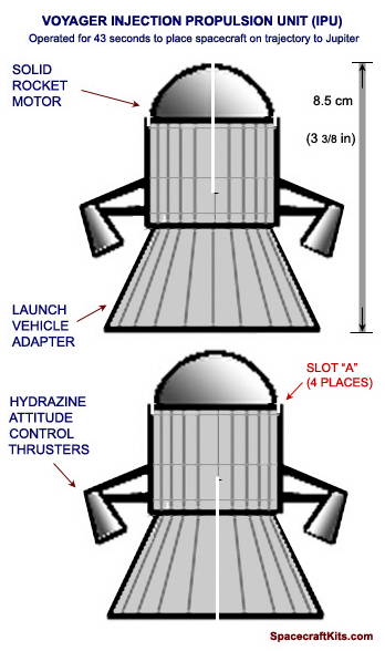
Also, a rudimentary model piece is provided on this web page, to print and cut out, to represent Voyager's Injection Propulsion Unit, showing how Voyager was configured for launch. See image at right. It is left to the serious modeler to fabricate a more realistic IPU if desired. You might like to read a technical description of how the IPU functioned for 43 seconds, firing a solid-propellant rocket motor to begin Voyager's near-Hohmann transfer orbit to Jupiter. Please look on Amazon, or Barnes and Noble, or your favorite book store, for Deep Space Craft, An Overview of Interplanetary Flight. The Voyager IPU is discussed in Chapter 4.
Instructions for assembling your model in its flight configuration (fully deployed) are here).
1. ASSEMBLE THE MODEL ACCODING TO THE DEFAULT INSTRUCTIONS
- First assemble your Voyager model according to the instructions for Flight Configuration, but as you proceed, pay attention to the three special call-outs for the Launch Configuration. They appear in red type. For example, you don't have to assemble the MAGNETOMETER BOOM because during launch it was stowed within a small cannister.
2. ASSEMBLE THE INJECTION PROPULSION UNIT
 Click on the thumbnail at right to bring up a full-size image of the rudimentary model part representing the Voyager Injection Propulsion Unit (IPU). Print a copy of the image on card stock. If you wish, print a second copy on lightweight paper to glue to the back of the card stock hardcopy so detail can be seen from any angle. Click on the thumbnail at right to bring up a full-size image of the rudimentary model part representing the Voyager Injection Propulsion Unit (IPU). Print a copy of the image on card stock. If you wish, print a second copy on lightweight paper to glue to the back of the card stock hardcopy so detail can be seen from any angle.
- Check the size of your hardcopy to be sure the parts are very close to the measurements shown (8.5 cm high). If necessary, adjust the print size and reprint until the size is satisfactory.
- Using an art knife with a sharp new blade, cut out the two parts from your card stock hardcopy. Don't neglect the central slot on each part. Cut out and glue the second copy to the back of the parts, to show detail on both sides, if desired.
- Join the two cutout pieces at right angles, slot into slot. Secure with glue and let dry.
- Bend each of the four HYDRAZINE THRUSTER units over in the same direction about 45 degrees (see illustration at top of page). This completed your IPU.
3. MOUNT YOUR VOYAGER ON THE IPU
- Set your completed Voyager model (Flight Configuration) atop the completed IPU so that the bottom of each of its four struts engages in a small slot marked SLOT "A" in red on the IPU part sheet.
- Adjust your Voyager model to be level and straight atop the IPU. Secure with glue and let dry.
4. STOW THE BOOMS
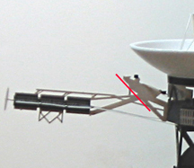
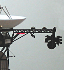
- Cut the RTG BOOM supports where shown by the red line in the image at right. The two horizontal struts can be left intact, since they will fold.
|
|
- Rotate the RTG BOOM 90 degrees to point downward. Glue the recently cut end onto the support, and glue the ends of the RTG's small struts, which look like this:
 onto the side of the IPU where they touch. For placement, see the image of the completed Launch Configuration at the bottom of this page. Crease the two horizontal struts roughly mid-length. onto the side of the IPU where they touch. For placement, see the image of the completed Launch Configuration at the bottom of this page. Crease the two horizontal struts roughly mid-length.
- Cut the SCIENCE BOOM supports where shown by the red line in the image at right. The lower strut can be left intact, since it will fold.
|
|
- Rotate the SCIENCE BOOM 90 degrees to point downward. Glue the recently cut end onto the two supports as seen in the image below, and glue the edge of the SCAN PLATFORM to the IPU where it touches, referring to the image below for placement. Crease the long thin support at about mid-length.
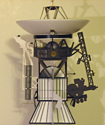
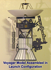
THIS COMPLETES YOUR LAUNCH CONFIGURATION ASSEMBLY
Again, note that it is rudimentary, but it shows how the Voyager-1 and Voyager-2 spacecraft appeared when they were placed inside the aerodynamic fairings atop their Titan-III-E launch vehicles in 1977. An experienced model maker may wish to research the appearance at more length, and modify this model configuration substantially.
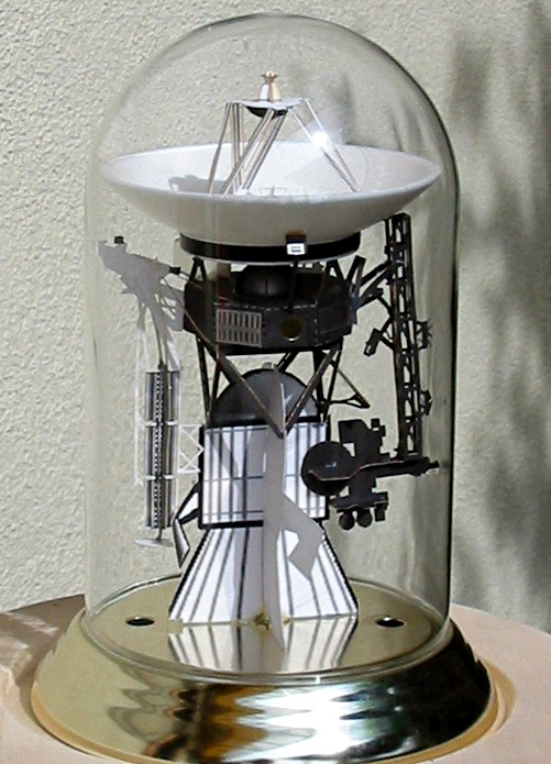
| Your completed Voyager in Launch Configuration can be installed within a 4.5-inch diameter bell-jar. The glass bell-jar at right (click to enlarge) used to house a (faux) rotating (torsional) pendulum style clock, called an anniversary clock, such as this one, which sold for about $15. It demonstrates nicely how the spacecraft was designed to fit within the launch fairing atop the Titan-IIIE launch vehicle in 1977 at the beginning of its journey through the galaxy.
|

|
| BACK TO VOYAGER ASSEMBLY INSTRUCTIONS |
| SCI HOME PAGE |
|