|
Voyager SCIENCE KIT
Version 4.7
|
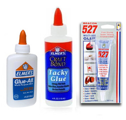 Use regular white glue (
|
|

|
|
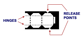
Identify HINGES which join segments of some parts for easy folding.
- In general, if it matters which direction something must fold or be positioned,the instructions will say so. If not stated, use any convenient orientation.
- Sections marked * may be accomplished at the same time if more than one person are working on assembly, or if you wish to work on one section while glue dries on another section.
* 1. ASSEMBLE THE COMMUNICATIONS ANTENNA.
(If you're using the HGA Assembly 3D-print file, or the fully printed object from our new Shapeways shop, you may skip most of this step. Go directly to the SUN SENSOR step just before 2. ASSEMBLE THE SPACECRAFT BUS.)
- With a piece of fine sandpaper, or denim, wipe the edges of the plastic HIGH GAIN ANTENNA Dish (HGA) to remove any rough edges if necessary to improve its appearence. Use caution not to scratch the soft plastic foam with your fingernails.
- With a pen or pencil, mark the inside center of the plastic HGA. Holding the HGA up to a strong light may help you identify the center, where it has a small dense circle of plastic foam. With a very sharp, new art knife, make two slits all the way through the center, at right angles in a + pattern, with the slits crossing at the center mark. Each slit should be about half a cm (or 1/4 inch) long. Go in from above. The bottom center of the HGA will crumble into a shower of little plastic particles. You may want to catch them in a cup.
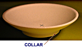
- OPTIONAL: Apply 1/4-inch (6 mm) wide black tape around the outside of the HGA collar to more accurately represent the actual Voyager's appearance.
- From sheet A, release the two halves of the FEEDCONE. Join at right angles, one slot into another, and insert the narrow end down into your cross-slits in the HGA. Stand it straight up inside the HGA and secure with white glue (or use "527 glue" as described above for better strength).
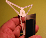
- Release the TRIPOD from sheet B. Turn the side with the "J" away from you. Press the edge of a metal ruler (or straightedge) down lengthwise into the middle of each leg to crease it slightly. This will add rigidity to the tripod, keeping the legs nice and straight. To do this easily, you might try placing the TRIPOD down on top of three of four layers of folded paper towel, and then pressing down strongly with your straight edge onto the center of the TRIPOD legs. You only need to impart a slight crease to make it rigid.
- Release two halves of the SUBREFLECTOR from sheet B. Slide together at right angles, slot into slot. Insert into the cross-slot in the center of the TRIPOD (J-side up), keeping the SUBREFLECTOR's J-shaped feature closest to the slot marked "J" in the TRIPOD. Adjust the flat portions of the SUBREFLECTOR into flush contact with the TRIPOD. Secure with glue and let dry.
- Bend all the TRIPOD legs down, making a crease at each of the short black lines up near the SUBREFLECTOR. This will allow the tripod to stand on its own.
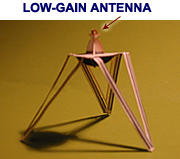
- Release the small gold circular LGA (Low-Gain Antenna) from sheet A. Glue its center cross-slot over the top of the SUBREFLECTOR assembly, gold side up.
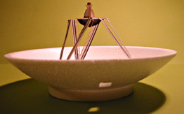
- Stand the TRIPOD inside the HGA with the leg tips at about the same radius as the collar. Adjust the tripod so that the subreflector is level and centered above the FEEDCONE. Secure the tip of one leg to the HGA with glue (again, use "527 glue" as described above for best strength) and let dry. Then secure the remaining legs, keeping the SUBREFLECTOR level and centered.
- Place the HGA in front of you with the "J" mark on the subreflector pointing directly away from you. Measure up 1 cm (3/8 inch) from the top of the collar (outside) directly in front of you, and place a dot. With a sharp new art knife, carefully cut a 7 mm square out of the HGA, centered on your mark. (The square hole's sides are to be "square" with a tangent to the HGA's collar.) 7 mm is the width of the gold portion of the SUN SENSOR on Sheet A, which will need to lodge into this hole in the HGA in the next step. Refer to the SUN SENSOR on sheet A to size the hole correctly.
- Release the SUN SENSOR from sheet A. Fold its gold tab back (toward the all-black side) about 90 degrees. Insert the gold end of the SUN SENSOR up into the square hole in the HGA from below. Gold faces upward into the HGA. The gold should end up about flush with the inside of the HGA, the tip of the gold panel pointing toward the HGA's center, and obscuring much of the square hole. The silver marked panel faces outward below the HGA, and protrudes downward. Secure with glue ("527 glue" if desired) in the HGA. Once the glue has dried, fold the SUN SENSOR's long black leg up temporarily to keep it out of your way.
* 2. ASSEMBLE THE SPACECRAFT BUS.
- From sheet A, release the long, 10-segmented SPACECRAFT BUS. Bend so it becomes roughly circular, with the gold and silver outside. Each segment is called a BAY. Pinch a crease into each of the nine hinges between the BAYs.
- Position the tab at the end of the BUS between the ears at the other end. Bend the tab over flush with the front, and glue. The BUS is now a closed decagon.
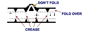
- Identify the upper side of the SPACECRAFT BUS. It is the side with three triangular members and seven smaller hinged tabs. One at a time, fold over the seven tabs on the SPACECRAFT BUS upper side, toward the inside of the decagon. Do not bend the three triangular members.
- Release the BUS SUPPORT from sheet B, and trim off any remaining rough edges. Position it up inside the BUS, where it will contact the white sides of the bent tabs. Glue each bent tab to the BUS SUPPORT. This will hold the BUS's decagonal shape.
- From sheet B, release two circular halves of the PROPELLANT TANK. Join at right angles, slot into slot, and insert it into the cross slots in the middle of the BUS SUPPORT. Place it halfway in, straighten, and glue.
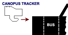
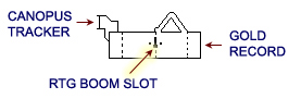
- From sheet A, release the CANOPUS TRACKER. Crease the hinges so it becomes U-shaped, silver outside. On the SPACECRAFT BUS, locate the one bay that contains two vertical keyhole-shaped slots. Position the CANOPUS TRACKER on top of the bus so the two tabs slide into the slots on the bay. Secure with glue only the tabs where they meet the side of the SPACECRAFT BUS. Do not apply glue where it meets the top of the BUS.
- Bend up the ten bottom sections of the SPACECRAFT BUS toward the center, forming shelves at right angles to the bays.
* 3. ASSEMBLE THE STRUTS.
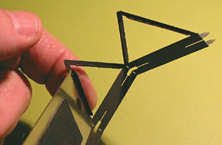
- From sheet B, release the STRUTS. Notice that each of the eight struts has a narrow hinged panel. Fold each of these eight hinged panels on over in the same direction (toward what will become the inside of the assembly). It might help to use a straightedge to make the creases.
- The four triangular segments are joined by hinges. Crease the hinges so the piece forms a rectangle. (The hinged panels from previous step point toward the inside of the rectangle). Insert the two white tabs on one end, into the slots on the other end and glue. When the glue dries, snip off the two protruding white tabs.
- From sheet B, release the TARGET PLATE. Fold the short black tab back away from the gray side. Fold the longer, Y-shaped tab in the same direction.
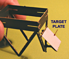
- On one of the STRUTS triangular leg set, there are two parallel horizontal bars with slots. Insert the small rectangular black tab atop the TARGET PLATE into the middle of the longer slot. Insert the tip of the longer Y-shaped tab into the shorter slot near the bottom of the STRUTS assembly. The grey side of the TARGET PLATE should be facing out. Apply glue.
4. ATTACH THE STRUTS TO THE SPACECRAFT BUS.
- Set the STRUTS in front of you with the TARGET PLATE on the right, and the pointed ends of the struts touching the table.
- Hold the SPACECRAFT BUS with the gold RECORD facing you. Set the SPACECRAFT BUS down on top of the STRUTS, keeping the bay with the gold record parallel to the side of the STRUTS which is facing you.
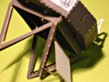
- Maintaining this alignment, slip the lower shelves of the SPACECRAFT BUS into the corner-slots at the top of the STRUTS, at the TARGET PLATE end. Two adjacent shelves will fit into each complete corner-slot.
- Squeeze the STRUTS assembly so the 3 remaining sides flex in toward the middle. This will allow you to work the STRUTS assembly up inside the bottom of the bus until the remaining corner-slots engage the remaining shelves. Work the SPACECRAFT BUS shelves, at the side opposite the TARGET PLATE, into the remaining corner slots. Again, two adjacent shelves will fit into each complete corner-slot.
- Straighten out anything deformed by squeezing, and re-align the bays if necessary so the gold record is parallel to the front side of the STRUTS. Apply glue where the SPACECRAFT BUS meets the two corners of the STRUTS assembly near the TARGET PLATE only. Don't glue the other corners yet.
* 5. ASSEMBLE THE SCIENCE BOOM.
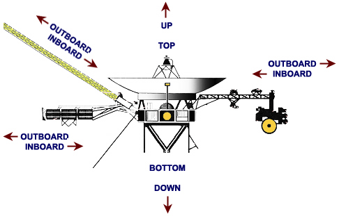
- From sheet A, release the SCIENCE BOOM. Compare it to the diagram below. Hold it so that the side with silver & gold is facing up. Fold the OUTBOARD END down away from you at a right angle, making a crease where it joins the truss panels.
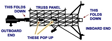
- Fold each of the truss panels down, forming a box shape. Two instruments will pop up.
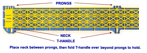
- Engage the two T & Prong latches to hold its shape. Secure with glue.
- Fold the square at the INBOARD END down to finish the box.
- Set the OUTBOARD END in position, perpendicular to the truss-panel boom. You'll notice that it can be latched in place, with a hook and notch, to hold its position. Apply glue.
- From sheet A, release the two parts of the SCAN PLATFORM, labeled 1/2 and 2/2. Locate the slot beside the silver circles on the larger part. At this slot, join the two halves at right angles, slot into slot, placing the silvered side of the smaller part facing the silver circles on the larger part. (These slots are each about 1 mm too long, so don't engage them all the way.) Apply glue and allow to dry. Make sure they remain at right angles. Let these dry thoroughly before proceeding.
- There is one remaining slot on the completed SCAN PLATFORM assembly. Join this slot at right angles with the long slot on the OUTBOARD END of the SCIENCE BOOM, slot into slot. It will fit only if the silvered parts are toward the outboard end. As you fit the slots together all the way, you'll notice part of the assembly extends down across the gold circle. This represents the secondary mirror of the instrument, and the gold circle represents the primary mirror. Adjust so the secondary is centered with respect to the primary. Apply glue, but avoid smearing glue onto the gold circle. Prop the assembly up so that all bends will remain at right angles as the glue dries.
*
6. ASSEMBLE THE MAGNETOMETER BOOM.
(Skip this step if you are assembling your model in launch configuration.)
(If you are using The Voyager MAG Boom 3D-print file, or the fully printed object from our new Shapeways shop, you'll have to perform this step a bit differently than instructed below.)
- Carefully release the outboard half of the MAGNETOMETER BOOM from sheet A. Snip each release point as far as possible away from the part, as close as possible to the parts sheet.
- Notice that the MAGNETOMETER BOOM is made up of three long truss panels connected to each other by tiny hinges. Carefully fold the truss panels so
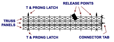 the boom becomes triangular in cross section. Gold faces outside. Crease the hinge points carefully without creasing any of the trusswork. Engage the T & Prong latch near the middle, and apply a small dot of glue to secure the boom together at that point. Let dry.
- When the middle has dried, engage the two remaining T & Prong latches and glue the boom together at those points. Do them one at a time, letting the glue dry in between. Keep an eye on them as they dry, in case any latches pop open.
- After the glue has dried, apply another tiny drop of glue to join the trusses at every crossmember. Let dry. After it has dried, carefully trim off all the release points and any protruding T & Prong latches.
- OPTION: At this point, decide whether to use the full scale length MAGNETOMETER BOOM or only half. If your model will be handled a lot, use only the outboard section. Also, be aware that the full-length version might sag if kept in a highly humid environment. On the other hand, if your model will be on display, and will not be moved or handled very much, you may want to use the full scale length boom. If you opt to use only the outboard section, skip ahead to step 7.
- Assemble the INBOARD half of the MAGNETOMETER BOOM from Sheet B, using the same process as for the outboard half.
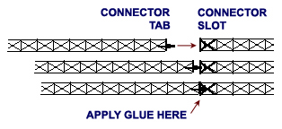
- When both sections of the MAGNETOMETER BOOM have dried, attach them together: Insert the connector tab of the outboard section into the connector slot of the inboard section, and slide the center truss panels together. Make sure both sections of the boom are in line. Apply a small bead of glue at the connector tab-slot, and let dry.
- When the tab/slot glue is dry, turn the boom over so that the tab/slot joint is on the bottom. Apply a small bead of glue to the apex, above the tab/slot. Adjust, if necessary, so that the two sections are straight in line with each other, and let dry. When dry, apply a few more tiny beads of glue to join the sections on all 3 sides. Note: applying too much glue, or applying all the glue at once, will soak and deform the delicate structure.
* 7. ASSEMBLE THE RTG BOOM.
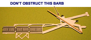
- Release the RTG BOOM (VERTICAL) from sheet B. Glue a toothpick in place on one side of the part, as shown at right (skip this toothpick if you're assembling for launch configuration). Note: the toothpick is now at the INBOARD end of the RTG BOOM, where it will later attach to the spacecraft. This will provide strength to support the MAGNETOMETER BOOM. Wait for glue to dry.
- Take a look at the RTG BOOM (HORIZONTAL) on sheet B. The long struts that form an open triangle are on the INBOARD side of the piece. The two white tabs at the extreme inboard end of these struts will later attach to the spacecraft.
- Release the RTG BOOM (HORIZONTAL) from sheet B. Press a straightedge into each of the two long struts to stiffen them by intruducing a slight crease down the struts' centers, the same way you did with the TRIPOD legs in step 1.
- Pick up the RTG BOOM (VERTICAL) and slide its slot at right angles, into the slot on the HORIZONTAL member between its two struts. Secure with glue, and be sure the parts remain at right angles as the glue dries.
- Release the circular, silver PLUME SHIELD from sheet A. Place its central slot over the T- shaped tab at the end of the RTG BOOM (HORIZONTAL). The silver should face outboard. The PLUME SHIELD should remain out at the end of the tab, up against the top of the T. Apply glue to hold it at right angles to the rest of the boom. When dry, trim the protruding end of the T. Note: the PLUME SHIELD is now at the OUTBOARD end of the RTG BOOM.
8. ATTACH RTG BOOM TO SPACECRAFT BUS.
- Identify the keyhole-shaped RTG BOOM SLOT between two bays in the BUS. Note this slot is between two tiny circular holes:
- Identify the RTG BOOM's single connecting tab at the inboard end of RTG BOOM (VERTICAL). See image below right.
- Insert the RTG BOOM's single connecting tab into RTG BOOM slot. Slide the tab up to lock in place in the slot. Apply glue, but avoid getting any glue into the pinholes on either side of RTG BOOM slot. Let the glue dry before proceeding.
- Work the two tabs on the RTG BOOM (HORIZONTAL) underneath the SPACECRAFT BUS, and into the corner slots of the STRUTS assembly, where they meet the SPACECRAFT BUS. Adjust the RTG BOOM so that it points straight out. Check its alignment by sighting across fromthe opposite side. Secure with glue. Turn the assembly upside down, and rest it on a table while the glue dries. Let dry before proceeding.
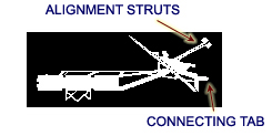
- Identify two ALIGNMENT STRUTS extending out from the RTG BOOM:
- Bend the bottom ALIGNMENT STRUT down towards the CANOPUS TRACKER and glue its end to the top of the SPACECRAFT BUS near (or under) the CANOPUS TRACKER. Keep toothpick aligned with center of the RTG BOOM as they protrude outboard from the SPACECRAFT BUS.
- Bend the top ALIGNMENT STRUT down in the opposite direction, pass it through the triangular HGA support, and glue its end on top of the bus, so that the toothpick remains aligned with the RTG BOOM pointing outboard from the SPACECRAFT BUS. Both of the ALIGNMENT STRUTS should be fairly taut. Let dry.
9. ATTACH SCIENCE BOOM TO THE SPACECRAFT BUS.
- Find two keyhole-shaped slots centered on two adjacent bays of the SPACECRAFT BUS above the TARGET PLATE. Insert the tabs on the struts of SCIENCE BOOM into the slots. Slide tabs upward to lock in place. Apply glue, and align SCIENCE BOOM straight out and level from bus. If it tends to angle upwards too much, bend it down a little so it will stay straight out and level. Secure with glue. Set model down on its STRUTS, and it will balance. Allow glue to dry before continuing.
10. ATTACH THE HGA TO THE BUS.
- Place HGA assembly upside-down on a beverage cup to hold it steady. That is, with the TRIPOD going down inside the cup.
- Identify the 3 triangular HGA supports on the SPACECRAFT BUS. Bend these outboard slightly, so they point outboard a few degrees. Give one top-corner of each support a little twist to point it further outward. Apply glue (use "527 glue" for best strength) to these 3 tips. Very carefully place it, upside down, onto HGA so that the tips adhere to the bottom edge of the HGA's collar. Do this in such a way that the SUN SENSOR will be directly above the gold record on SPACECRAFT BUS. (In the next step below, the SUN SENSOR's long black leg will have to extend straight down towards the gold record. The HGA should be level with SPACECRAFT BUS. Wait for glue to dry, then set the model upright. You're nearly finished.
- Insert the SUN SENSOR's thin black end down into the slot above the gold record on the SPACECRAFT BUS. Adjust the length of the SUN SENSOR leg by pushing it down into the SPACECRAFT BUS, until it is straight. Secure with white glue to the SPACECRAFT BUS.
11. ATTACH THE MAGNETOMETER BOOM.
- OPTIONAL: You may wish to stiffen the MAGNETOMETER BOOM to prevent it from warping over time, especially in very humid areas. If so, insert a very thin piece of balsa wood (about 3mm or 1/8-inch in diameter, and 40 cm or 16 inches in length for the full-length boom) inside the MAGNETOMETER BOOM, and apply a few drops of glue along its length to connect it with the boom. A couple of cm, or an inch, of the balsa wood should protrude from the inboard end of the boom to facilitate connecting it to the spacecraft, modifying the next steps. Allow glue to dry.
- Pick up the MAGNETOMETER BOOM at the inboard end, which is opposite the end with the gold rectangle. Slip the inboard end of the boom down over the toothpick.
- If your MAGNETOMETER BOOM is full-length, having both inboard and outboard halves together, the following applies: Turn the boom so that the slot in one panel of the inboard end will fit over the barb on the RTG boom where it meets the toothpick. Slip the inboard end of the boom down over the toothpick. Squeeze the end of the boom slightly as you gently push it down over the barb until it snaps into place.
- If your MAGNETOMETER BOOM is half-length, consisting of only the outboard half, the following applies: First bend the barb on the RTG boom down around the toothpick so it will be out of the way. Then slip the inboard end of the boom down over the toothpick.
- Apply glue sparingly at the inboard end of the MAGNETOMETER boom and along the toothpick inside the boom. Let dry.
- OPTIONAL: Paint the toothpick white.
12. OPTIONAL: INSTALL PRA/PWS WIRES.
(Skip this step if you are assembling your model in launch configuration.)
These add a key visual character to the model. But install ONLY if your intended use of the model would not present any hazard of eye injury.
- Straighten some thin (18 gauge) copper wire. This can be done by securing one end to a stationary object like a vice, gripping the other end firmly with pliers, and pulling until the wire stretches slightly. Protect eyes should wire snap. Cut into two 20-cm (8-inch) lengths. Bend a tip of each wire into a small circle, using pliers, to reduce the possibility of eye injury.
- Hold the SPACECRAFT BUS with the RTG BOOM facing you, and notice two pinholes in the BUS, one on either side of the central RTG BOOM member.
- Guide one wire under the right-hand RTG BOOM strut (as the RTG BOOM faces you), and insert it into the pinhole on the right hand side. Guide the end of the wire up inside the bus until it comes in contact with the BUS SUPPORT.
- Repeat the procedure with the other wire, guiding it up from underneath the left-hand RTG BOOM strut, and going into the left-hand pinhole.
- Adjust positioning of the wires so that they are at right angles with each other, and also at right angles with MAGNETOMETER BOOM. Secure with glue where they touch the BUS SUPPORT and at the pinholes. You might want to cut wires to table-top level so your model will stand on its own.
C. YOU'VE FINISHED YOUR MODEL
Now that you're familiar with the names of all of the spacecraft's major structures, and some of its instruments, the associated Fact Sheet will point out the rest of the instruments, and explain what everything on the spacecraft is for. The Presentation Guide suggests ways to simulate Voyager's space flight operations activities, in case you want to do so. The finished model can also sit on a shelf, as long as the bottom tips of the STRUTS are glued to a base such as a small piece of polished wood, or a slab of acrylic. It might help to balance the model on its base if you install a small wire hook in the base where it can engage with the tab at the bottom of the TARGET PLATE. Give some thought to ways of supporting the MAGNETOMETER BOOM, since the full-scale version might sag if kept in high humidity, or if the model is handled very much. To hang your model from the ceiling, alone or in a mobile, tie a thread or nylon fishing line to the model. You may want to do this in such a way that the MAGNETOMETER BOOM points nearly straight up or down, to minimize the chance that it will ever develop a sag.
D. ABOUT YOUR VOYAGER MODEL
It is made of 100% recycled paper (Halopaque Satin 60 lb cover). The HGA is made of expanded polystyrene (EPS) foam, which contains less than 15% recycled material. It is recyclable. Your model's scale is approximately 1/30. The optional PRA/PWS antenna wires are much thicker than scale, but only about 50% scale length, to avoid sagging in one G. The MAGNETOMETER BOOM very accurately represents the fiberglass structure on the spacecraft, but it can support itself in one G, while the spacecraft's boom cannot; it supports massive instruments (the magnetometers, which are represented on your model by gold rectangles). The EPS HGA is four times thicker than scale, and incorporates a spherical figure instead of the spacecraft's parabolic figure. The optional 3D-printed HGA assembly has the correct parabolic curve, and its thickness is closer to scale.
DO YOU HAVE TWO VOYAGER MODELS?
One for Voyager 1, and one for Voyager 2, of course! Or one in Flight Configuration, and one in Launch Config?
SCI Space Craft International
P.O. Box 61027 Catalina StationPasadena, California 91116-7027 U.S.A.
Space Craft™ SCIENCE KITS are made in the U.S.A. using recycled materials and advanced processes. Copyright © 2014 SCI Space Craft International
Sections marked with a * may be accomplished at the same time if two or more people are working on assembly, or if you wish to work on one section while glue dries on another.
| SCI HOME PAGE |