|
*
2. ASSEMBLE THE SPACECRAFT BUS.
View the whole assembled model
Lunar Prospector's SPACECRAFT BUS houses supporting subsystems, such as radio gear for communications with Earth, propulsion for adjusting the orbit, spin, and attitude, optical devices to provide attitude control knowledge, and mechanical support and deployment mechanisms for the science instrument booms.

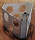
- Cut out the SPACECRAFT BUS part from Sheet 1. Cut out the six ovals, and the three circles, marked X. Lightly score each of the six vertical lines within the part.
- Apply glue to the rectangle marked GLUE. Fold back, away from the printed side, on each of the six scored lines, and overlap the glue with the opposite end. Squeeze the seam until dry.
- Adjust the angles of each fold to be equal. The object protruding above, by the way, represents optical devices used for attitude control and navigation. Their fields of view are toward the +X direction.
- Print Parts Sheet 2 onto white card stock. Cut out the BOOM AND TANK SUPPORT.

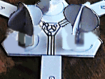
- Cut out the six PROPELLANT TANK HALVES. Slit each along the vertical line, and then fit pairs of circles together, slot into slot, at right angles. Fold tab Z over 90 degrees, so you can stand the tank upright. These parts represent spherical tanks which hold propellant. (Optionally, you might want to replace these with some spherical objects of the same size.)
- Apply glue to the end, near tab Z, of one PROPELLANT TANK, and stand it, centered in a circle on the BOOM AND TANK SUPPORT. Repeat with the remaining tanks.
The markings in the part's center, by the way, represent the mechanism which reeled out three restraining tapes to deploy the booms, which spring out, uncoiling, from their canisters.
- Find a letter printed on each protruding rectangle. They indicate particular science instruments supported by booms: A for APS/NS, G for GRS, M for MAG/ER. Find the same letters printed on the SPACECRAFT BUS part.

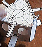
- Work the BOOM AND TANK SUPPORT up inside the SPACECRAFT BUS, inserting each of the rectangles through its corresponding circular hole, from inside the SPACECRAFT BUS: rectangle A through hole A, etc. Tanks face up. Adjust so that the SUPPORT is level and even, and its rectangles rest as low as they can in each circular hole. Secure with glue where each rectangle protrudes from a hole. Add a little more glue inside where the parts touch. Wait for the glue to dry.
The photo in this DRAFT version shows the tanks too short. They should be centered within the six ports on the spacecraft bus piece.
- Cut out the SPACECRAFT BUS TOP from Sheet 2. Fold the small tab Z up, away toward the printed side, about 80 degrees, on each of the two arms.

- Set the SPACECRAFT BUS TOP (shown in the image) into the upper end of the SPACECRAFT BUS, at right angles to it, rotated so that the arm marked o is above the rectangle marked M. Printing faces up. This piece fits just inside the SPACECRAFT BUS, supported by its protruding arms. Glue in place.
- Cut out the SPACECRAFT BUS BOTTOM from Sheet 2. Cut out the circle marked X. Fold the small tab Z back, away from the printed side, about 80 degrees, on each of the three arms.
- Turn the SPACECRAFT BUS upside down. Set the SPACECRAFT BUS BOTTOM (not illustrated) into the lower end of the SPACECRAFT BUS, at right angles to it, rotated so that the arm marked -X is parallel to the rectangle marked G. Printing faces down, toward the outside. This piece fits just inside the SPACECRAFT BUS, supported by its protruding arms. Glue in place.
| GO ON TO THE NEXT STEP |
| INSTRUCTIONS FIRST PAGE |
|


