|
3. ASSEMBLE THE LOWER TELESCOPE TUBE.
View the whole assembled model
- From both Sheets DE, remove a LOWER TELESCOPE TUBE 1/2. Using a straightedge, fold back all the hinged panels in the same direction. Make both parts exactly the same. Be very careful not to tear any of the members as you fold them.
If you're confident enough with an art knife, score the hinges slightly using the knife and a straightedge before folding. This will make for a straighter fold, but be careful not to cut through the hinges. Place the pieces down on a flat surface and press creases into all the folds, flattening and straightening each part, again taking care not to tear or pull apart.
- Place both halves of the LOWER TELESCOPE TUBE down on a flat surface in the orientation shown in the sketch below, folds pointing up. Overlap the two points on each piece as shown by 1.5 mm or 1/16 inch, and join them with glue. Use a straightedge to make sure both parts remain straight in line with each other.
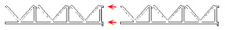
- Bring the opposite ends of the combined LOWER TELESCOPE TUBE around to meet each other in a ring, with the folded panels facing inward. The part will naturally begin to form a rectangle. Allow this to happen, letting bends occur only where there are vertical members between trusses.
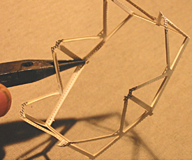 Overlap the two points on either end, and glue together as before. Press together till the glue dries. In the image at right, long-nose pliers are being used to squeeze together the glue joints.
Let the glue dry thoroughly before proceeding.
- Bend the ring into a hexagon by creasing at each vertical member.
- The 6 crosshatched points indicate the top of the hexagonal ring. Pinch a crease into each of the crosshatched points. This will further define the hexagonal shape of the LOWER TELESCOPE TUBE.
- Adjust the fold in each of the six long members which form the bottom of the hexagonal ring so that they are perpendicular to the vertical members, still pointing inward.
+
+
+
+
+
- Examine the 6 corner slots on the bottom of the ELEVATION RING (the bottom edge has the platforms) to be sure they are open and clear. Reopen them with an art knife if necessary. Set the ELEVATION RING down with the bottom (the platform side) facing up.
- Align LOWER TELESCOPE TUBE with each of its crosshatched points sitting on a corner slot in the bottom of the ELEVATION RING. Gently work one crosshatched point partially into a slot. Work around LOWER TELESCOPE TUBE, inserting each remaining crosshatched point partially into a slot on the ELEVATION RING.
- After all 6 crosshatched points have been started into corner slots in the ELEVATION RING, press the whole LOWER TELESCOPE TUBE gently in, until all the crosshatching has disappeared inside the corner slots, and it is level and neat. See below. Apply glue at each point where a truss enters the ELEVATION RING, to fasten the LOWER TELESCOPE TUBE. Let the glue dry.
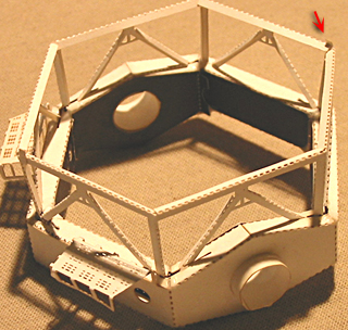
- Snip off the two tabs protruding from the bottom of the LOWER TELESCOPE TUBE (see red arrow in the image above) so that it can sit on a flat surface without rocking or tilting.
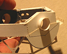
- From Sheet DE release an ELEVATION DRIVE GEAR. Apply glue near the small arc and press in place up under the ELEVATION BEARING on the outside of the ELEVATION RING. Its large arc extends down in the same direction as the LOWER TELESCOPE TUBE.
Adjust so it's centered and even, using its printed black lines as an outline of the ELEVATION RING behind it. See image at right.
THIS COMPLETES THE LOWER TELESCOPE TUBE.
View the whole assembled model
| GO ON TO THE NEXT STEP |
| INSTRUCTIONS FIRST PAGE |
| SCI HOME PAGE |
|