|
4. ASSEMBLE THE MIRROR CELL.
View the whole assembled model
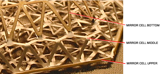
- From Sheet A, release the hexagonal MIRROR CELL UPPER. Using a straightedge, fold all 6 hinged edge panels over the same direction to stiffen the edges. Lay it on a flat surface and press a crease into your folds. The direction in which the hinged edge panels are folded will be called the BOTTOM.

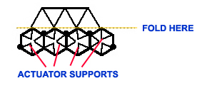
- Notice 36 triangular structures with three prongs inside. The prongs represent the ACTUATORS which support the mirror cells (for details, see the Fact Sheet, and the back of Sheet A).
- Locate one of these structures out near a corner of the hexagonal MIRROR CELL UPPER. Insert a pencil or a toothpick, going in from the BOTTOM of the MIRROR CELL UPPER, and bend all 3 ACTUATORS up toward the top side of the MIRROR CELL UPPER. Crease each one so it will remain standing straight up or nearly so.
- Repeat the above step for 5 more sets of ACTUATORS: one nearest each of the 5 remaining corners of the hexagonal MIRROR CELL UPPER.
- Optional, to add extra realism (which will NOT be easily visible in your completed model) repeat the procedure for all 36 sets of ACTUATORS.
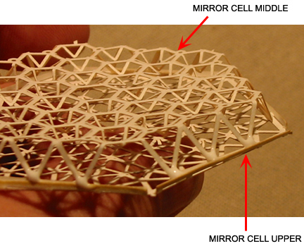
- From Sheet A, release the MIRROR CELL MIDDLE. Around the outside of the piece, identify 6 groups of three triangles that are connected by a bar at their outer edge. Using a straightedge, fold these down, to about 90°. The points to fold are indicated by (almost invisible) small yellow marks on the part. The direction in which they are folded will be called the TOP side of the MIRROR CELL MIDDLE.
- Insert a pencil (a hexagonal pencil works very well) in from the BOTTOM of the MIRROR CELL MIDDLE, into the space between one set of three triangular ACTUATOR SUPPORTS, pushing them out toward the top of the MIRROR CELL MIDDLE.
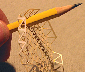 Push the pencil all the way through and wiggle it around to bend up the three small triangles.
When you withdraw the pencil, the 3 ACTUATOR SUPPORTS should be bent upward about 45 degrees. Let them remain at that angle.
- Repeat for all 36 sets of ACTUATOR SUPPORTS.
NOTE: In the Keck Telescope, the ACTUATOR SUPPORTS extend from the MIRROR CELL MIDDLE up to the base of the ACTUATORS in the MIRROR CELL UPPER to support them. In the model, ACTUATOR SUPPORTS are by design too short. They help illustrate the concept, though, and they add to visual character of vertical structure in mirror cell.
- Now pick up the MIRROR CELL UPPER (from the first steps on this page), and turn it over with its BOTTOM facing up. The ACTUATORS will be facing down. To protect them, you might want to support the MIRROR CELL UPPER by its edges with strips of corrugated cardboard.
- Take the MIRROR CELL MIDDLE and turn it over so its TOP is facing down. Place it down onto the MIRROR CELL UPPER, aligning the folded sets of triangles with the outer edges of the MIRROR CELL UPPER. Slip one set of the folded triangles which are joined by a bar, inside the folded-up outer edge of the MIRROR CELL UPPER, and glue it in place.
When the glue dries, repeat with each of the remaining sets of folded triangles.
Important: keep the central holes in the MIRROR CELL UPPER, MIDDLE, and BOTTOM pieces aligned vertically as you glue them together.
- From Sheet A, release the MIRROR CELL BOTTOM. Identify the six sets of six triangles, each of which has a faint yellow mark where it should bend.
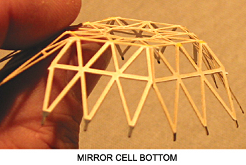 Bend down each outer set of triangles about 45 degrees, making the fold where the yellow marks appear, using a straightedge. The direction in which the triangles fold will be called the TOP.
- Turn the MIRROR CELL BOTTOM over so the TOP points down, and insert a set of its 3 black pointed tabs into a set of 3 circular holes on the MIRROR CELL MIDDLE. Slip the tabs completely down into the holes. Secure each tab with a drop of glue and let dry.
When dry, repeat with the remaining five sets of 3 black tabs. Let each set dry before proceeding.
- Adjust the folded sections of the MIRROR CELL BOTTOM to close up any gaps between sections of adjacent triangles, outboard of the yellow fold marks, and join the sections with glue.
+
+
+
+
+
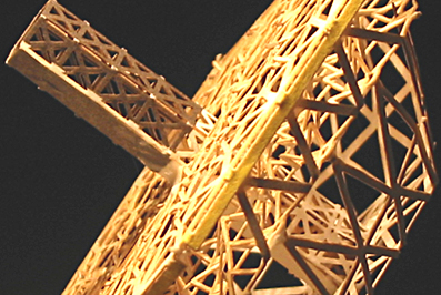
- From Sheet A release the TERTIARY TOWER. Notice that it is made up of 6 long panels: 5 of trusswork, and 1 solid, all joined by hinges. Place a crease in each of the 5 sets of hinges, causing it to take a pencil-like, tubular shape.
Glue the edges together to hold its tubular shape. It may be helpful to wrap it around a hexagonal pencil to apply the glue. DO NOT apply any glue to the last trusswork section of the white end.
- After the glue dries, fold each of the 6 tiny trusswork panels at the white end outward about 30 degrees to widen the end. This is the BOTTOM of the TERTIARY TOWER.
- Holding it by the bottom end, insert the TERTIARY TOWER up into the central hole in the MIRROR CELL BOTTOM. Gently twist it until it aligns with the hexagonal opening in the center of the MIRROR CELL MIDDLE and goes through. Guide it all the way in, until the bottom of the TERTIARY TOWER is about flush with the MIRROR CELL BOTTOM.
- Apply glue around the bottom of the TERTIARY TOWER to join it to the MIRROR CELL BOTTOM. Before the glue dries, adjust the TERTIARY TOWER so it is perpendicular to the MIRROR CELL UPPER. Apply glue where it touches the MIRROR CELL UPPER.
The image below shows the TERTIARY TOWER in place in the MIRROR CELL.
+
+
+
+
+
- Adjust ACTUATORS on top of MIRROR CELL UPPER to be straight up, if they might have bent down during handling.
- From Sheet A, release the PRIMARY MIRROR. Examine the markings on the back, non-reflective side (this will be the last time you will be able to inspect them), and compare with the illustration on the back of Parts Sheet A.
With the reflective side facing up, slip the PRIMARY MIRROR down over the TERTIARY TOWER, and into contact with the ACTUATORS. Align the PRIMARY MIRROR so the rows of mirror segments are parallel with the edges of the MIRROR CELL UPPER. Adjust the central hole in the PRIMARY MIRROR so the TERTIARY TOWER is centered in it. This demonstrates the proper alignment.
- Remove the PRIMARY MIRROR , and apply droplets of glue to the tips of several of the ACTUATORS on the MIRROR CELL UPPER. Put the PRIMARY MIRROR back into position, maintaining the proper alignment as it comes in contact with the glue-tipped ACTUATORS. Let dry. This completes the MIRROR CELL.
NOTE: In the actual Keck Telescope, the mirror segments were not installed until all of the major structural assembly was completed. Also, each of the actuators connects with a whiffletree (see description on the back of Sheet A), a connection which is not actually replicated in your model.
+
+
+
+
+
- Notice which side of the TERTIARY TOWER is solid, rather then truss. The solid portion represents a crawlway. This will be its FRONT.
- Examine the ELEVATION RING. Hold it with the ELEVATION BEARINGs on the left and right sides, and the two platforms facing away from you. The FRONT is identified as the side opposite the two platforms.
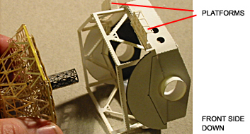
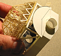
- Apply glue along the bottom of the LOWER TELESCOPE TUBE. Position the completed MIRROR CELL below the LOWER TELESCOPE TUBE, with the TERTIARY TOWER pointing up inside the ELEVATION RING. Turn the MIRROR CELL so that the FRONT of the TERTIARY TOWER faces the FRONT of the ELEVATION RING: away from the side which supports the two platforms.
- Press together, and adjust the bottom of the LOWER TELESCOPE TUBE to align as closely as possible with the MIRROR CELL. Hold until the glue dries.
- From Sheet A, release the TERTIARY MIRROR. Curl it into a cylinder so that the square tab at one end overlaps the opposite edge. It may help to wrap it around a stick. The reflective oval represents the actual tertiary mirror. It should remain flat. Apply glue to the tab and the edge of the piece, overlap about 1 mm. To judge exactly how much to overlap, try fitting the TERTIARY MIRROR cylinder down inside the top of the TERTIARY TOWER. It should fit snugly. Press the ends together, and let dry.
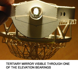
- Bend the reflective oval back inside the tiny cylinder 45 degrees. Insert the cylinder down into the top of the TERTIARY TOWER, turned so that the mirror is directly visible through one of the ELEVATION BEARINGS (either one). Glue in place, unless you prefer to have it free to turn, illustrating its true operation.
THIS COMPLETES THE MIRROR CELL.
View the whole assembled model
| GO ON TO THE NEXT STEP |
| INSTRUCTIONS FIRST PAGE |
| SCI HOME PAGE |
|